

KablatiCAD allows users to create different representations of an electrical installation within the same project, including planimetric diagrams, single-line diagrams, multi-line diagrams, functional diagrams, and assembly simulations.
It is also possible to run a circuit simulation and observe how the system behaves in response to user actions and events occurring during operation.
KablatiCAD was developed primarily for educational and training purposes.
One project, multiple representations
An electrical installation can be represented in different ways depending on the aspect being studied.
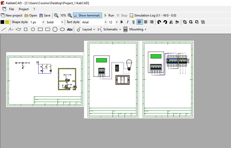
KablatiCAD allows these different representations to be included within the same project, using as many drawing sheets as necessary.
For example, a project can include:
- one or more sheets containing the planimetric representation of the installation;
- a single-line diagram;
- a multi-line diagram;
- a functional diagram;
- one or more sheets dedicated to component assembly;
- additional sheets to expand the project.
The sheets can be arranged side by side horizontally. The entire project can therefore be explored by moving left and right without having to manually switch between individual sheets.
This approach makes it possible to keep the different representations of an installation within the same environment and easily move from one part of the project to another.
Planimetric diagram
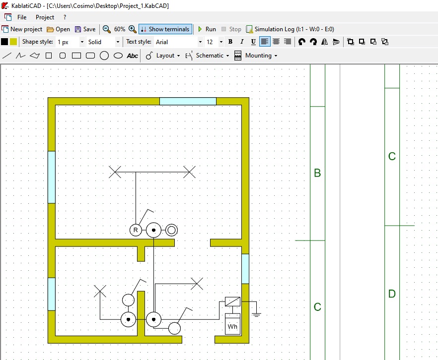
KablatiCAD provides a collection of graphical symbols for planimetric diagrams.
Components of the electrical installation can be represented directly on the floor plan, allowing the installation to be drawn within the different areas of a building.
The planimetric representation can be included together with the other representations of the same project, making it possible to relate the physical position of the components to the corresponding electrical diagrams.
Single-line and multi-line diagrams
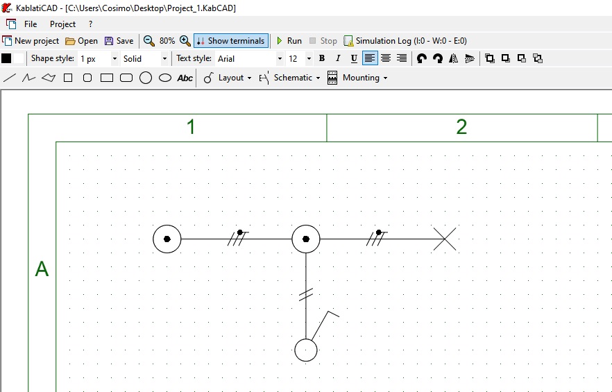
The software provides graphical symbols for creating single-line and multi-line diagrams.
These diagrams can be placed on one or more project sheets, allowing electrical connections to be represented with the level of detail required by the exercise.
The use of multiple sheets also makes it possible to divide larger diagrams into smaller and more easily readable sections.
Functional diagram
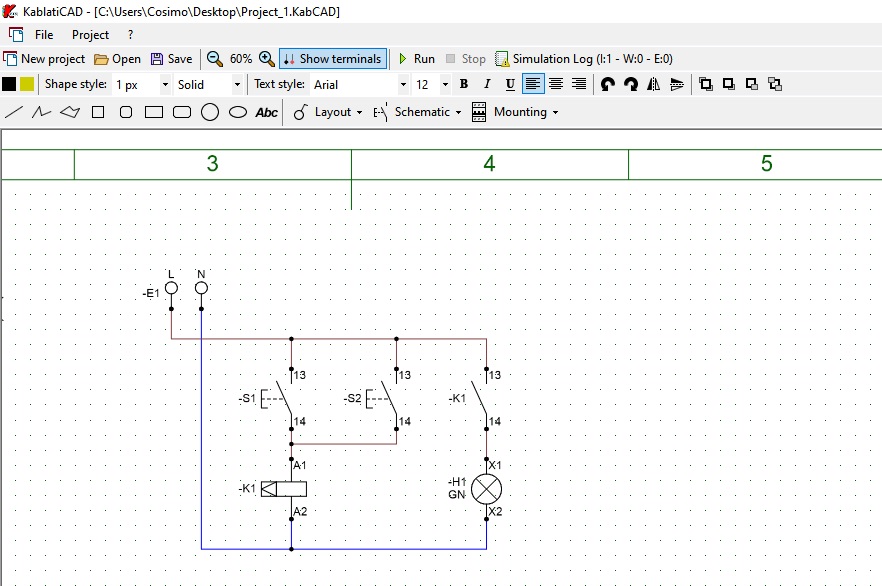
A dedicated section of KablatiCAD contains graphical symbols for functional diagrams.
Functional diagrams allow the operating logic of a circuit and the relationships between its different devices to be represented.
They can be used together with the planimetric representation and wiring diagrams to study the same installation from different perspectives.
Assembly simulation
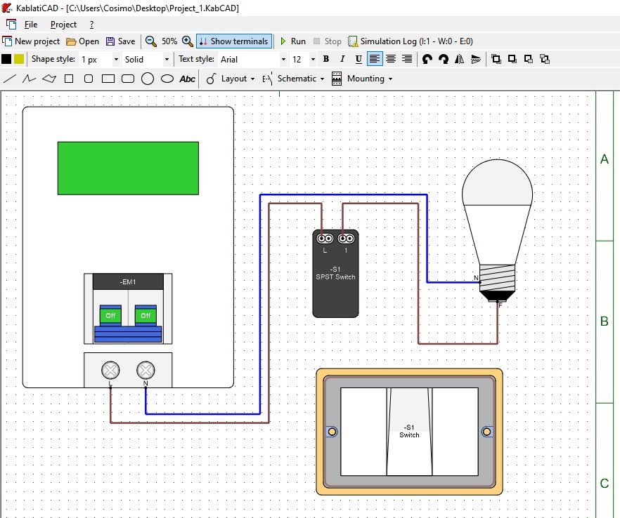
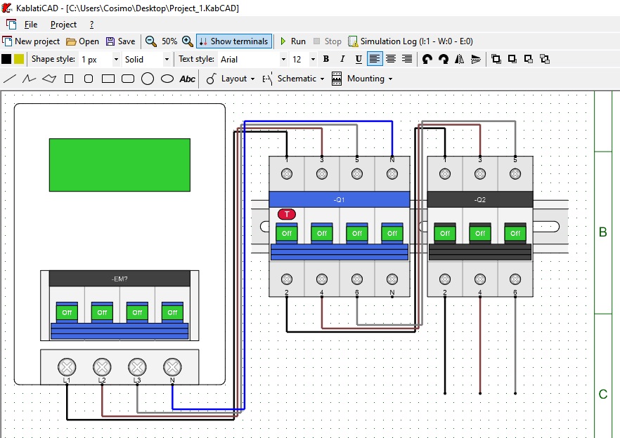
KablatiCAD includes a section dedicated to the representation and simulation of component assembly.
The simulation includes both typical residential electrical installations and configurations using devices installed on DIN rail.
Residential installations
For residential electrical installations, it is possible to create and simulate configurations such as:
- one-way lighting circuits;
- two-way switching circuits;
- intermediate switching circuits;
- relay-controlled circuits;
- other switching and lighting configurations.
These configurations can be used to create exercises and observe how the different devices operate during the simulation.
DIN rail components
For simulations involving modular devices installed on DIN rail, several components are available, including:
- miniature circuit breakers;
- residual current devices;
- modular relays;
- timers;
- other modular devices.
It is therefore possible to represent the arrangement of components on the DIN rail and use it as part of the simulation project.
The components currently used in the assembly representation are created as graphical drawings. In the future, they may be replaced or complemented by more realistic representations of the actual devices.
Circuit simulation
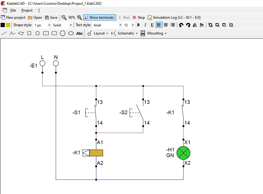
Once the project has been created, KablatiCAD allows the circuit simulation to be run.
During the simulation, it is possible to observe the behaviour of the installation in response to user actions and events generated by the circuit.
For example, it is possible to observe what happens when:
- a push button is pressed;
- a control is activated;
- the state of a device changes;
- a timer expires;
- other components are activated or deactivated.
In this way, the project is not limited to being a graphical representation: it is possible to observe the behaviour of the circuit and verify its operating logic as the different devices interact during the simulation.
Simulation log
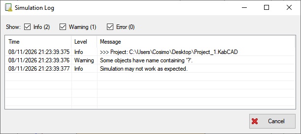
During the simulation, a dedicated log window is available to monitor the events generated by the circuit.
The log displays information about the simulation and distinguishes between:
- warnings, which indicate abnormal situations or conditions that do not prevent the simulation from continuing;
- errors, which indicate blocking conditions that prevent the simulation from continuing correctly.
The log is therefore useful both for understanding what happens during the simulation and for identifying possible problems in the circuit configuration.
Projects on multiple sheets
A project can consist of an arbitrary number of drawing sheets. It can start with a single sheet, and additional sheets can be added as the size of the exercise requires.
The sheets are arranged side by side horizontally, and the workspace can be moved left and right to explore the entire project.
This approach makes it possible to keep planimetric representations, electrical diagrams, functional diagrams, and assembly representations within the same project, without having to manually switch between the sheets being displayed.
Designed for education
KablatiCAD was created with the goal of bringing together aspects that are often studied separately.
Students can start with the representation of an installation, create its electrical diagrams, represent the assembly of its components, and finally run the simulation to observe how the circuit behaves.
The software can therefore be used for exercises involving:
- reading and creating electrical diagrams;
- planimetric representation of electrical installations;
- single-line and multi-line diagrams;
- functional diagrams;
- the relationship between diagrams and assembly;
- residential electrical installations;
- modular devices installed on DIN rail;
- circuit operation;
- identifying errors during simulation.
The goal is to provide a tool that allows users to move from the graphical representation to the simulated behaviour of an electrical installation within the same project.
Under continuous development
KablatiCAD is a project under development.
The components used in the assembly simulation are currently represented using graphical drawings. A possible future development is the introduction of more realistic representations of the devices.
The number of components, configurations, and exercises may also be expanded as the software continues to evolve.
Terms of Use
KablatiCAD is distributed free of charge by the author and was developed for educational and training purposes.
The software is provided “as is”. The author does not guarantee the absence of errors in technical drawings, calculations, or simulations.
The simulation is intended exclusively for educational and training purposes and does not constitute a technical verification, certification, or validation for the construction or implementation of real systems.
Any practical implementation must be verified and carried out under the supervision of qualified technical personnel.
For complete information regarding the use of the software, please refer to the KablatiCAD Terms of Use.
Requirements
Operating system: Microsoft Windows with .NET Framework 4.8.1